Introduction and Overview
Cisco DNA Center (DNAC) is the orchestration platform for designing, provisioning, and implementing policies on the network. It provides visibility into the network and an understanding of the user experience with network services. It collects telemetry from existing multiple devices, applications and users, applies advanced algorithms to uncover correlated insights and suggest remediation. This helps in minimizing troubleshooting time by identifying the root cause of issues on the network. DNAC generates health scores for client, network and applications in use; these are compiled from different metrics.
With Cisco DNA:
- One gains full visibility of the network
- It is possible to predict network performance and issues
- Rapidly troubleshoot issues.
The DNA Center Assurance landing page provides summaries of network and client health. The network health displays health summaries (in percentages) of switches, routers, wireless LAN controllers, and access points. The client health displays summaries of wireless and wired clients.
Cisco DNA includes guided remediation which provides suggestions for correcting a detected issue.
A demo version of Cisco DNA Center can be found at the URL https://dcloud-dna-center-inst-rtp.cisco.com/dna/home. Login access uses the following credentials: username: demo password: demo1234!
SD-Access and DNA Setup
The following discussion on Cisco DNA Center is based on version 2.2.2.8 released on 17/June/2022. Other Cisco DNA Center releases can be found here.

The DNA Center version in use can be determined by clicking the "About" icon at the top right.

SD-Access fabric, in a campus network enables the maintenance of network policies to a roaming user regardless of their location. SD-Access uses IS-IS as the underlay protocol and LIST-VXLAN+TrustSec in the overlay protocol to allow users with their devices to be onboarded onto the network and maintain their same network configuration anywhere on the network.
The SD-fabric is created by DNA center. A guided workflow is used to setup the entire SD-fabric. DNA Center is made up of four main modules. The following is a simplified sitemap of the DNA modules:
- Design: design of the physical layout of the network is developed
including the addresses of the buildings, and geographical locations. Features that
can be configured under Design include:
- Network Hierarchy: create organizational hierarchies. Import and export of hierarchies is supported. The two export options are sites or maps.
- Network Settings: consists of the following:
- Network: Configure AAA, NTP and Image Distribution (SFTP) servers. Once devices are discovered, DNAC will deploy using these settings. Other settings are DNS server, message of the day (MoTD) with the option to not override the device MoTD; default is to override the device MoTD. These settings can be applied to a site or to all sites (global).
- Device Credentials: credentials for CLI, SNMP (v2c and v3 - read and write), HTTP(S) - read and write.
- IP Address pools: Address pools consist of the IP CIDR, gateway, DHCP and DNS servers for the various subnets of the organization. IPv4 and IPv6 address pools are supported.
- SP Profiles: QoS settings.
- Wireless: Wireless networks configured with the settings for:
- SSID
- Level of security (Enterprise or personal, WPA 2 or WPA 3)
- Type of network: voice and data or data only.
- Wireless option: dual band operation, dual band operation with band select, 2,4GHz only, 5GHz only.
- AAA authentication
- Fast transition(802.11r) configuration
- Telemetry: Configure Syslog, traps, and NetFlow properties for devices. DNAC will deploy these settings after the devices have been assigned to a site or provisioned.
- Image Repository: contains images for devices (physical and virtual) on the network.
- Network Profiles: profiles supported are for Firewall, NFVIS, Wireless, Switching, Routing, Telemetry Appliance
- Authentication Template
- Policy: identify the end-users and end-points and access authorizations.
- AI Endpoint Analytics
- Group-Based Access Control
- Application
- Traffic Copy
- Virtual Network
- Provision: discover the network devices and onboard them.
Additionally, provision module enables the creation of the network access fabric.
- Network Devices:
- Inventory: list of managed network devices and their sites of allocation
- Plug and Play: detected network devices (through device discovery), can be assigned to a site and become managed devices
- Inventory Insights
- Fabric
- Services
- Service Catalog
- Cisco User Defined Network
- Application Visibility
- Stealthwatch Security Analytics
- App Hosting for Switches
- Umbrella
- Site to Site VPN
- Cloud
- Network Devices:
- Assurance: monitor and troubleshoot the network.
- Dashboards
- Health
- Issues
- Sensors
- Wi-Fi 6
- Rogue and aWIPS
- PoE
- Dashboard Library
- AI Network Analytics
- Network Insights
- Network Healthmap
- Peer Comparison
- Network Comparison
- Baselines
- Manage
- Issue Settings
- Health Score Settings
- Sensors
- Intelligent Capture Settings
- Dashboards
To be able to gain insights into the performance of the network, DNA should be setup and devices enrolled. The procedure to setup DNAC is as follows:
- Install DNAC
- Create a site hierarchy: where the locations, building, floors are defined.
- Run discovery: using IP range, CDP or LLDP
- Inventory collection: DNA detects the devices
- Device manageability: DNA auto-pushes configuration to the device to enable it send telemetry to DNA
- Provision Devices: Assign devices to site/building/floor previously defined.
- Devices ready for assurance
Network devices such as APs, switches, routers, firewalls are enrolled into DNAC.
These devices typically run on IOS-XE such as catalyst 9000
series switches, ISR-4400 series routers.
DNA center communicates with these devices using programmability protocols
NETCONF/RESTCONF. When DNA Center communicates with devices using NETCONF/RESTCONF,
it creates a telemetry subscription through which the devices can stream data
such as CPU, memory utilization, interface counters, ACL counters; basically all output
from show commands are streamed to the DNA Center. DNA Center stores this information
and logs it into a database with the timestamp of occurrence. This enables understanding
these parameters across a time range. The information collected is from network
devices as well as client information.
DNA Center applies machine learning to this collected telemetry information to
provide insights into the network performance and lists any detected issues
degrading the network.
Design Network Hierarchy Structure
The DNA container hierarchy is divided into groups:
- Areas high-level logical subdivisions. All areas are children of the Global area. Areas can contain other areas or buildings.
- Buildings: actual physical locations. Buildings have a geo-location. Buildings can contain floors/floor plans.
- Floors: physical sub-divided space in or out of a building.
Network Discovery
For devices to be managed, they must first be discovered. The discovery feature:
- Scans the network for network devices
- Inventories discovered devices
- Can configure required network settings (if not already present).
- The SNMP credential is for DNAC discovery
- For SSH access, credentials should have the privilege level 15 for DNAC to be able to configure devices with appropriate commands when applying policies or resolving detected issues.
Discovery supports the following types of device discovery:
- CDP: connect to a seed device and learn the next hop devices of the seed device. This process is repeated on the neighboring devices to the seed device to discover other devices.
- IP address or range: scans the designated IP address range with ICMP to identify responding devices.
- LLDP: operates similarly to CDP.
In DNA Center, to access the device discovery feature, Tools → Discovery

To create a new discovery, select Add Discovery. The following page is opened.


At least one CLI credential and one SNMP credential is required. NETCONF is required for 9800 series switches.
Add Device
A new device can be added manually through the Inventory tab under the Provisioning module. This is done by selecting the "Add Device" button. The following parameters are required when adding a new device:
- Device type: options available include: network device, compute device, Meraki dashboard, Firepower Management Center.
- Credentials: preconfigured credentials are selected for;
- CLI
- SNMP credential, version, retries and timeout values.
- HTTP(S) credential and port number
- NETCONF port
- Authentication protocol: SSH or Telnet

Select "View Inventory" to view the newly added devices. To add the device to a site: Select "Actions", then Provision, then "Assign Device to Site". The serial number and device type are displayed to confirm the device and as well as the list of all sites. Discovered devices are added to the inventory by DNA. After initial discovery, DNAC maintains the inventory by polling the devices in inventory, by default, every 25 minutes to determine reachability. This can be modified to up to 24 hours. By default, only devices that have been active for less than a day are displayed.
Device Credentials
DNAC requires a set of global credentials to use when enrolling the devices into DNAC. These settings are the same as Discovery credential sets:
- CLI credentials: username, password and enable password. This local user should have a privilege level of 15.
- SNMPv2 / SNMPv3: SNMPv2 read/write community string (SNMPv3 is optional).
- HTTPS (Optional): read/write string, username, password and port.
Credential sets define common global credentials, specified in global container, and instance specific credential sets, specified per container, for network devices in a discovery. Credentials in higher-level containers are inherited by lower level containers. DNAC allows multiple credentials to be specified for a defined credential type. Support for exceptions (non-common) credentials can be included in discovery.
In DNAC, these credentials can be added from the Design → Network Settings → Device Credentials.

The credentials can be set for the Global site or lower site in the organizational hierarchy. Credentials configured at the global level will be inherited by the sites under the Global location.

If a list of credentials is available for a given site, select the appropriate credential that will be used by clicking the radio button of that corresponding credential.
DNAC automation can add missing credential sets to devices upon discovery for example if the CLI credentials are available but SNMP configuration is not working, DNA is able to access the device using the CLI credentials and enable SNMP with the configuration that was not previously functional but entered into DNA during the device enrolment. If multiple credentials are configured, DNA will start with the first credential, then the second, third ... up to the credential that works. DNA will remember the credential that worked for a given device.
Different device types are managed through different credential types:
- SSH: standard Cisco devices.
- CLI: standard Cisco devices.
- SNMP: standard Cisco devices.
- HTTP(S): NFVIS devices
- NETCONF: all supported devices such as Cisco XE devices
For discovery to work, the required ports include:
- Ping: ICMP echo and reply.
- SSH: TCP port 22
- SNMP Poll: UDP port 161
- SNMP Trap: UDP port 162
- Syslog: UDP port 514
- NetFlow: UDP port 6007 or TCP 443
At a minimum, CLI and SNMP details are required for DNAC to discover devices. For SNMPv2c community read-only string is required. For SSH/Telnet device access, the user account should have a privilege level of 15.
The protocol order of the credentials can be specified. The options include SSH and Telnet. If Telnet is enabled, a warning message gets displayed about the insecure nature of Telnet.
Device Controllability
Device controllability is a feature that is enabled, by default, when adding a device to inventory from the Inventory page or through discovery. Device Controllability operates as follows:
- If DNAC could not connect to the device using any of the SNMP credentials provided, but could connect using the CLI credentials, then DNAC will configure the first SNMP credential available in the request.
- If available, the first SNMPv3 credential will be configured instead of SNMPv2c.
- If NETCONF support exists in the device and DNAC could not connect to the device using NETCONF but could connect to the CLI credentials, then DNAC will configure NETCONF on the first port provided in the request.
- NETCONF is supported on Polaris images version 16.5 or higher.
Configuration Changes on Wireless LAN Controllers (WLC)
During the network discovery process, there are several changes that DNAC automatically makes to WLCs:
- Installs a certificate for streaming telemetry: this certificate secures all communications between DNAC and the device. This certificate is installed for all devices i.e., routers, switches, WLCs etc.
- Configure streaming telemetry service (WSA)
DNAC becomes the network assurance service for that WLC from the start.
Configuration Changes on Switches
There are several changes that DNAC automatically makes to switches during discovery:
- PKI
- IPDT
- HTTP server source interface is configured
- SNMP RO & RW communities (if not configured).
  crypto pki trustpoint DNAC-CA

    enrollment mode ra

    enrollment terminal

    usage ssl-client

    revocation-check crl

  crypto pki certificate chain DNAC-CA

    <snip>

    quit


  device-tracking tracking

  !

  device-tracking policy IPDT_MAX_10

    limit address-count 10

    no protocol udp

    tracking enable

    !

  interface <ACCESS-INTERFACES>

    device-tracking attach-policy IPDT_MAX_10


  ip http client source-interface Loopback0


  snmp-server community <RO-COMMUNITY> ro

  snmp-server community <RW-COMMUNITY> rw
If an ACL is configured for SNMP community string, DNAC may remove the ACL during discovery. Remember to add the ACL after the DNAC discovery is complete.
Device Controllability in Host Tracking
When device discovery is performed with "Device Controllability" enabled, DNAC will enable IP device tracking(IPDT) on discovered devices. IPDT is activated on switch ports operating in the switchport access mode. IP Device Tracking keeps track of connected hosts on a switch. IPDT sends an ARP probe on that access interface to check that the device is alive. This ARP is not propagated out any other port. This helps in tracking where clients are connected in the network. By default, switches use MAC-address tracking for monitoring connected hosts. If a device is connected to the network but is silent (not accessing network services) MAC addresses timeout in the MAC address cache on the switch. This will assume that the device is off the network. With IPDT, the MAC address of a connected device is not allowed to timeout. When the MAC address timer is close to expiry, an ARP probe is sent out that particular access port that the device is connected to and when the device responds, the MAC address timer is reset.
Configuration Changes on Routers
There are several changes that DNAC automatically makes to routers during discovery:
- PKI: certificate to ensure confidentiality between DNAC and the router.
- HTTP server source interface is configured.
- SNMP RO & RW communities are enabled if not already configured.
  crypto pki trustpoint DNAC-CA

    enrollment mode ra

    enrollment terminal

    usage ssl-client

    revocation-check crl

  crypto pki certificate chain DNAC-CA

    <snip>

    quit


  ip http client source-interface Loopback0


  snmp-server community <RO-COMMUNITY> ro

  snmp-server community <RW-COMMUNITY> rw
Telemetry
Device Provisioning
When device discovery is completed, a newly added device is placed under the Global site and categorized under "unassigned devices". Unassigned devices not not have a site allocation. Assurance requires devices to be assigned to a site in order to push telemetry. It is important to assign a device to a site. This is because network telemetry may not be received for the device if it is not assigned to a site. Assigning a device to a site does not push configuration to the device.
Telemetry
Syslog, SNMP and NetFlow properties can be configured for DNA Center managed devices. DNA Center will apply these configurations to the devices when they are assigned to a site or provisioned. DNA Center can be configured to be the SNMP trap server, syslog server or NetFlow collector server. Optionally, external servers can be configured in DNA Center for export of the telemetry data. By default, DNA Center is the SNMP server for managed devices.


Device Telemetry Profiles
Telemetry profiles can be configured to send Syslog, and NetFlow configs to supported devices. Telemetry profiles include two predefined profiles that send telemetry to DNA Center and one profile that does not send telemetry. Custom telemetry profiles can be added. The three default telemetry profiles for use in provisioning assurance configurations include: maximal, optimal and disable.
| Profile Name | Syslog level | NetFlow version |
| Maximal | Informational | IPFIX |
| Optimal | Informational | |
| Disable |
Profiles can be assigned at site or device level. The default telemetry profile is Disable. The recommendation is to apply Maximal to routers and Optimal to switches.
Custom telemetry profiles can also be created in exceptional use-cases where the best practice telemetry profile settings need to be altered. If custom telemetry profiles are configured and the device does not support the telemetry profile configurations e.g. NetFlow, then DNA will produce a notification message. The supported telemetry configuration will be pushed to DNA and the unsupported telemetry will not be pushed.

Telemetry profile push is used to assign profiles to specific devices and validate configuration push. If the predefined telemetry profiles are used, telemetry information gets pushed to DNAC immediately after being applied.
Verify assurance dashboards are being populated with expected telemetry data. DNAC sets itself up as a syslog server to be able to collect data from that device.

NetFlow
NetFlow data is required for Application Health data. DNA provisioning of NetFlow is only supported on routers running IOS v16 or newer. The current behaviour is for NetFlow to be enabled on all interfaces of routers.

DNA Center Dashboards
The landing page of DNA Center is the DNA Dashboard. The information displayed in the dashboard is aggregated over the last 24 hours.
DNA Center Assurance Issue Dashboard
The DNAC Assurance issue dashboard is a centralized view of network issues allowing one to quicky identify and diagnose network problems. It provides insights into problems and provides recommendations on how to resolve the problems. By default, issue data is saved for up to 30 days.
The issue table contains a list of issues categorized by priority. Additionally, some issues are flagged as being identified by AI.

Issue Status
Issues have three types of status: open, resolved, and ignored. When the issue is ignored, it is ignored for a specific time period. An issue can be resolved in two ways:
- Manually changing the status
- Auto-resolution mechanism; support for autoresolution is available for some issues; others are continually being added.
Issues are classified according to priority. The options are:
- P1: A critical issue that needs immediate attention which can result in wider impact on network operations.
- P2: A major issue that can potentially impact multiple devices or clients.
- P3: A minor issue that has a localized or minimal impact.
- P4: A warning issue that may not be an immediate problem but addressing it can optimize the network performance.
The issues dashboard can be filtered to display issues detected for a specific site

By default, the dashboard displays issues detected over the last 24 hours. However, this can be filtered for a time range of 3 hours, 24 hours or 7 days. Additionally, filtering can be done for a specified date range:

The following images show how to resolve a detected issue:


DNA Center Assurance Health
The DNA Center Assurance health section displays the health status of the network, clients and applications. The health dashboard also displays the Top 10 Issues detected which are categorized by priority.
The Network Health page can be accessed via the Assurance → Health. This view provides an aggregated score of the health of monitored devices for the defined time range.

Network Health
The Network Health section of the DNA Assurance center displays the health status of network equipment such as routers, switches, wireless LAN controllers (WLC), and access points (AP). It gives a snapshot of the device health over the past 15 minutes and 24 hours. A score is provided for the current state of health of the network. Network devices are categorized based on their role or type i.e., wireless, core, access, distribution switch, router.


Selecting a particular device with detected issues opens up Device 360 where the details of detected issues are displayed with the option to resolve the issues detected.
Device 360
Device 360 gives a full view of the device displaying the most detailed raw telemetry data received from the device. You can monitor and preview the health parameters of the network. Device 360 displays the following parameters:
- The current health score of the device: DNA monitors various parameters of
a network device. These parameters include:
- Memory utilization
- CPU utilization
- Data-plane parameters:
- Noise and air-quality for wireless
- Uplink availability
- Link errors
- The device details such as IP address, Product ID, and software version.
- The device health score on a 24-hour timeline by default. Other timeline options include 7 days.
- List of issues that occurred in the past 24-hours.
In the case of APs, the additional information collected includes:
- Number of clients connected
- Noise, air quality, interference

Device 360 provides a list of issues experienced by the network device. The timeline of the issues can be viewed by selecting the appropriate date/time. Suggested actions are provided on how to resolve any identified issues.
Device 360 includes a physical neighbor topology of the device. For a switch, it displays the clients connected and any uplink devices. This helps in determining the end-points that are affected when the switch or uplink device experiences a problem. The health score of the neighbors can also be determined by clicking on the neighboring devices in the physical topology.
Device 360 supports a pathtrace which enables performing a connectivity test between the device and a specified destination. It uses information learned from the network topology. It queries devices to, among other things, determine the availabilty of equal-cost multipaths. If intermediate devices are not managed e.g. MPLS, a cloud symbol is used to symbolize the unknown intermediate unmanaged devices.
Client Health
The client health page displays the health status of detected network clients. The following information is displayed about the clients:
- Client devices are listed and segregated between wired clients and wireless clients.
- Onboarding: A broken-down view of every step of the onboarding process is displayed making it possible to determine if the network infrastructure is causing the fault or the network service such as AAA. Clients that failed the onboarding process are displayed.
- For wireless networks, the following information is displayed:
- Client count per SSID
- Client roaming times
- Connectivity RSSI
- Connectivity SNR


Client 360
From the list of clients displayed under the page Health → Client, selecting a client opens up the Client 360 page for the client and it displays the following information:


Application Health
Application health dashboard processes application data and gives an insight into application performance. Application Health page displays information about how your applications are performing across the entire network. Applications are classified as business-relevant (such as Office 365 apps), business-irrelevant (such as Netflix), and default. Cisco application visibility is used to classify the applications. This classification is done based on the NBAR (Network-based application recognition). Application Health enables the monitoring of application statistics and application response. Application experience is based on NetFlow records exported by the routers. It correlates KPIs sources of the network to identify the problem domain faster and make issue resolution recommendations. Application health includes vital information such as business-class, traffic class, packet-loss percentage and latency. Application health can be accessed under DNA Assurance → Health → Application.
To receive application telemetry, ensure that:
- DNA discovers the required network devices
- Provision the device and assign it to a site
- Enable NetFlow telemetry collection for the devices


By default, the application health dashboard displays application packet loss, average throughput, network latency for business relevant applications.
Application 360
Selecting a specific application from the application health page displays the Application 360 page. The Application 360 page displays the details of the network experience of an application; these include:
- Issues experienced by the application such as network latency including the total number of occurences.
- Network devices exporting the application telemetry including:
- Usage in bytes
- Throughput in Kbps
- Packet loss
- Jitter
- Network latency
- Client network latency and server network latency
- Application server latency
- Application endpoints i.e. client devices using the application. Selecting a client device opens up the Client 360 page for the client.


SNMP Collector
DNA can also be used to collect SNMP traps and informs. DNA is the default SNMP collector. It pools network devices to gather telemetry data. By default, the following information is collected by SNMP:
- Device health: includes CPU utilization, memory, environment temperature, and device availability metrics. This information is gained through polling every 10 minutes by default.
- Interface health: includes interface availability and metrics.
- TCAM: polled
Software Image Management (SWIM)
Software management allows the installation, upgrade, and patching the embedded operating system running in managed devices such as switches, routers, APs, etc. DNAC stores and categorizes software images. It makes recommendations on latest software images based on vulnerabilities. It allows the standardization of software images for devices on the network.
Software Maintenance Update (SMU)
An SMU is a package that provides point fixes and rolls security resolutions to software images that have already been published. DNAC supports SMUs for IOS-XE versions 16.x onwards.
SMUs can be helpful:
- Due slower upgrade releases especially as software images require bug analysis, extensive testing, certification before official release.
- Due to faster availability of newer (improved) code to improve device performance or reporting
- When the time taken to copy images over slower VPN tunnels is significant.
- If business downtime during image upgrades is not within acceptable time-frames
Images Supported in SWIM
- Base images: all Cisco IOS, IOS-XE, AireOS, NX-OS images for supported devices
- Patches: patches (or SMU) are only supported on IOS-XE
- ROMMON: ROMMON is a firmware image on Cisco devices
- AP Device Pack (APDP): APDP allows quick support for newer AP outside DNAC release using the patching framework.
- AP Service Pack (APSP): allows quick support for point patches outside of DNAC release using the patching framework.
- Sub-package: allows deployment of sub-technologies on devices.
Image Repository
DNAC stores software images and software maintenance updates for the network devices. The image repository provides the following functions:
- Software images can be pushed to the devices.
- Stores software images of the devices on the network.
- Allows the designation of software images as golden. A golden image or SMU is a validated image that meets the compliance requirements of a particular device type. Designating a software image/SMU as golden saves time by eliminating the need to make repetitive configuration changes and ensures consistency across devices.

DNAC manages software and VNF (virtualization network functions) images. It also supports the management of third-party images. DNAC image management feature is accessible as a page under the Design module.
The DNA "Image Repository" page displays all images available. The "Delete" icon under "Action" indicates that an image has been downloaded to DNAC.
CCO credentials are the Cisco credentials for downloading firmware. These credentials can be used by DNA to access firmware repository. These credentials are configured in the DNAC "System Settings" page:

The following page displays image details with and without CCO configured:

With CCO configured, additional information about the image is provided compared to images without CCO information. If the CCO credentials are provided, DNAC provides guidance on the latest firmware updates and recommended images for a device.
When downloading image updates, the "Show Tasks" button shows download progress for firmware:

Distribution
DNAC uses the following protocols in their order of preference during the distribution of software images:
- HTTPS
- SCP
- SFTP
SWIM Times
| Latency | Should be less than 200ms between DNAC and the network devices |
| Distribution server | DNAC internal storage or remote file server particularly for geo-dispersed sites. |
| Protocol | HTTPS over SCP and SFTP |
| Software Version | The software image to be upgraded may
impact the upgrade process. The duration in the process for IOS-XE 17.3 is as follows:
|
SWIM Recommendations
- Distribute the software images first well ahead of the activation window.
- Leverage remote distribution support from Cisco DNA center for large geo-dispersed sites.
- If upgrading software images on a large number of devices, upgrade up to 500 devices at once. DNAC does the upgrade in a rolling batch of 100 each. Devices are upgraded as rolling list of 40 concurrent threads.
Image Upgrade
The image upgrade process in DNAC is a granular one. It supports image distribution and activation at once on demand. It allows the scheduling of these activities on individual time-frames to go hand-in-hand with the organization's maintenance windows. DNAC regularly monitors the network for compliance with the standardized images and raises notifications for devices with images that deviate from the set standards. DNAC makes pre and post installation/upgrade checks to ensure that integrity of the network is intact.
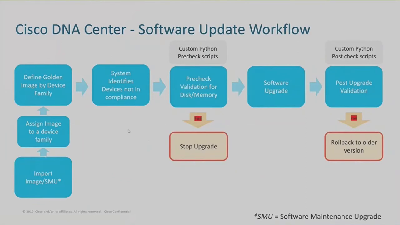
Most of these steps happen automatically
- Import Image/SMU: DNAC can be pointed to the Cisco firmware
download page. This will require the integration of image repository management
with Cisco where you provide DNAC with the required credentials to download the firmware.
Image management integration with Cisco involves accepting the EULA agreement to
unlock further image details:
- Get access to field notices and release notes.
- Get Cisco recommended image information.
- Get Cisco latest image information.
- Assign Image to a device family: so that the image is available to that device family.
- Define Golden image by device family: label a specific image as the golden image for that device family.
- System identifies devices not in compliance: DNAC checks the inventory for all devices that match that device family to establish the devices that are running that image and the ones that are not. DNAC then lets you know which devices are out-of-date.
- Precheck validation for disk and memory: checks for hardware requirements for the image upgrade. If any devices do not meet these minimum hardware requirements, the check fails and DNAC generates notification messages and the upgrade will not proceed. These checks are performed by custom Python precheck scripts. If the devices pass the minimum hardware requirements, the device is labelled as outdated and is ready for upgrade. The upgrade can then proceed for the device. The upgrade can be planned to be implemented immediately or at a scheduled time. The image can be pushed to flash memory
Devices requiring image upgrades can be viewed under Provisioning → Inventory → Focus →Software Images. The list of devices in inventory displays devices that require software image updates.

An image update readiness check is performed before the software image image upgrade takes place.

When upgrading software images for wireless infrastructure such as access points, and wireless LAN controllers, the protocol used for transfer of the images is SFTP. Additional support during wireless infrastructure image updates includes:
- Custom pre/post installation checks
- Sub-package support
- Rolling AP upgrade
- AP pre-download
- Upgrade of Aire OS/IOS-XE based controllers
- EWC upgrade workflow
- APDP updates
- APSP updates
For wired infrastructure such as switches, routers, firewalls, the following support is provided by DNAC during image upgrade:
- Protocols used are HTTPS, SCP and SFTP. The default protocol is HTTPS.
- Sub-package support
- ROMMON support
- Patches (SMU) support
- Custom pre/post checks
- Distributed SWIM
- Redundancies: stacks, VSS, SVL
- ISSU
When an image update has been activated for a device, DNA pushes the image to the device storage and starts the installation of the image. After a device completes an image update, DNA creates a wait period during which it expects the device to reboot and load the updated image. During this wait period, DNA may not update the status of the image on the device until after the wait period expires. DNA then carries out post-installation checks before updating the status in the DNA interface.
Troubleshooting using Cisco DNA Center
DNAC Assurance is the module of DNA that provides support with monitoring and troubleshooting of the network infrastrucure, client devices, and application performance. Most of the discussed features of DNAC assurance are used for troubleshooting purposes.
- Overall Health: The overall health page is a great starting point for troubleshooting network issues. This displays information learned about the network in the last 3 hours, 24 hours, or 7 days. This data is usually aggregated for the various geographical locations. The scope can be refined for locations, buildings and even floors.
- Network Health:
Get an overview of the health of the network and network devices. Information
is displayed in 5-minute intervals over the past 24 hours.
Network devices section lists all the devices with the following scores:
- Critical (1-3): displayed in red.
- Warning(4-7): displayed in amber/orange
- No errors(8-10): displayed in green
- No data(0): displayed in gray
- Client Health: Client 360 can be used to view all raw telemetry information of the device.
- Pathtrace: Pathtrace enables graphically seeing the path that applications and services take to reach the destination. Pathtrace is accessible Client 360 and Device 360.
- Network Time Travel: Can view the past history of device and client network data.
- Global Issues:
Access all issues: open, resolved or ignored. Issues are categorized as:
- Onboarding: Used to identify issues related to wireless and wired client onboarding.
- Connectivity: Used to identify issues related to network connectivity, including routing protocols (OSPF [Open Shortest Path First], BGP [Border Gateway Protocol]), and tunnels.
- Connected: Used to identify issues related to clients.
- Device: Used to identify issues related to the device, such as CPU, memory, fans, and so on.
- Availability: Used to identify any availability issues related to access points, wireless LAN controllers, and more.
- Utilization: Used to identify issues related to utilization of access points, wireless LAN controllers, radios, and more.
- Application: Used to identify issues related to application experience.
- Sensor Test: Used to identify any global sensor issues.